In our previous post we showed how to generate stable IR carrier signals using the ESP8266 NodeMCU module. A feature of the original approach was that the output IR signal was inverted and required some additional circuitry to invert it again before transmission. Since the original post we have figured out a method to output a non-inverted or standard IR signal thus removing the need for the additional circuitry. This is achieved by using what turned out to be a very simple setting hidden deep in the ESP8266 UART registers which is covered below. Like all simple solutions it also threw up some other quirks of the ESP8266 NodeMCU, which were eventually overcome with the addition of a simple resistor. The Updated ESP8266 NodeMCU Backdoor uPWM Hack for IR signals is detailed below – including updated source firmware, new circuit diagram and explanation of the ‘quirk’. Read on….

In this post we will focus only on the new information that is relevant. To understand the background to the uPWM hack please refer to our previous posts which go into more detail. Most users can simply upload the provided sketch for testing and thereafter amend it for their own purposes.
The SendIR module shown above is now available from our webshop.
The non-inverted Infrared Output
In the original uPWM hack the IR output is inverted because we are using the UART to generate (or hack) the IR carrier PWM signal. In an effort to find a workaround for this we recently began studying the Espressif ESP8266 Technical Reference manual and noticed some entries in the UART registers that seemed to suggest that all UART related pins could be individually set to operate in inverted form. For our needs this meant that we might be able to achieve ‘non-inverted’ IR output using our uPWM hack. The next step was to figure out how to achieve our objective in code using the Arduino IDE for ESP8266, which took some time. In the end it was a simple piece of code, as follows:
#include "uart_register.h"  // Place this at the top of the sketch

#define SET_PERI_REG_MASK(reg, mask) WRITE_PERI_REG((reg), (READ_PERI_REG(reg)|(mask)))
SET_PERI_REG_MASK(UART_CONF0(UART1) , BIT22);

//
This effectively sets bit 22 of the UART_CONF0 register of UART1 (Serial1 in Arduino) which tells the ESP8266 to invert the TX pin for UART1. Users should note that in order to get the best results the initUPWM, mark & space functions should be followed closely & where possible unchanged.
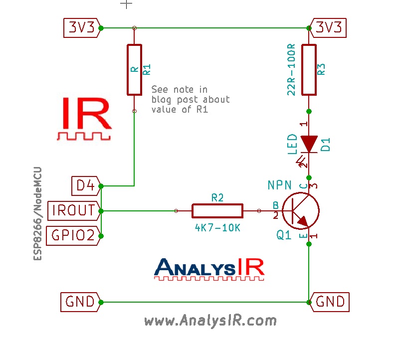
The updated IR Emitter Circuit

The uPWM Circuit diagram above for ESP8266 NodeMCU using UART shows the IROUT signal on pin D4 (GPIO2). You will notice that this circuit is much simpler than the previous one. R2 can be any resistor value from 4K7 to 10K or possibly less. Good values for R3 are from 22R to 100R with the smaller values producing more IR. If necessary you could try values lower than 22R, but be careful not to draw too much current from the 3V3 regulator. The value for R1 should be set such that after installation the resistance between D4 and 3V3 is between 3K and 4K. (See the ‘Quirk’ note below for more explanation). We suggest using either a TSAL6100, TSAL6200 or TSAL6400 as the IR LED. These Vishay LEDs are quality components. The transistor can be any NPN transistor like the 2N4401or similar.
SendIR
In the photo at the top we wired up one of our SendIR modules which features dual IR emitters, a constant current IR driver and selectable x1, x2, x3 IR output power (via jumpers). It can also operate via 5V or 3V3 supply. The SendIR module will be added to our shop in the near future and in the meantime you can contact us via the contact form at the top for instructions on how to purchase. Note that in the photo at the top we connected SendIR to the 5V USB supply instead of the 3V3 supply to ensure we could draw maximum current for the IR emitters and to avail of the extra IR power from the dual IR LEDs.
‘The Quirk’
The ESP8266 uses a number of pre-defined pins to signal how the boot up process should operate. Unfortunately D4 or GPIO2 is one of those pins and must be kept HIGH during the boot up process. On my system the pull-up resistor on GPIO2 is circa 10K and other modules use 3K. Depending on your particular module and the IR circuit you connect to GPIO2 the default pull-up may not function properly during boot up. If you experience an issue where the device does not boot up or allow firmware flashing after you connect your IR circuit then you need to do the following. Set the value for R1 such that the resistance between 3V3 and GPIO2(when powered off) is between 3K and 4K). On my test systems setting R1 to 5K or 5K8 worked fine. I suspect the more common 4K7 would also work fine. Of course you should only install R1 of you see problems with booting or flashing firmware. In the photo at the top, we have soldered an 0805 SMD resistor directly between D4 and 3V3 header pins for convenience – just where the white wire is soldered to D4/GPIO2.
Updated ESP8266 NodeMCU Backdoor uPWM Hack for IR signals
The updated sketch
You can get a copy of the updated firmware sketch by clicking here. The sketch shows how to send a range of IR signals from NEC to long Air Conditioner signals using both HEX and RAW formats. It sends a signal every 5 seconds and varies the carrier frequency between 30, 33, 36 ,38, 40 and 56 kHz.
If you find an interesting use for this firmware or embed it into a library then do let us know via the contact form linked above or our IRforum. Remember to credit AnalysIR as the original author and to include a link back to our website.