Our recent post about the silver bullet IR receiver proved very popular and we promised that we would follow-up with another variant of the poor maker’s Infrared receiver. This time we are using an IR Led (emitter), 2 resistors and any standard Arduino. You will also need to download the Arduino code provided below, compile and upload it. One of the most common problems encountered when trying to decode IR signals is that makers don’t always have the appropriate IR receiver for the job in hand or have to wait for one to be delivered by mail. Here we present an affordable method to allow you to use any IR emitter (LED) as a receiver and as a bonus we are publishing the Arduino code to make it all work.

The circuit presented above is very simple and comprises the following:
- R1 4.7K
- R2 22K
- IR Led (TSAL6x00 or equivalent), connected in reverse bias mode.
- Standard Arduino board
The ‘simplified’ theory of how this circuit works is as follows:
- R1 is connected between +5v and the cathode (-) terminal of the IR Led.
- R2 is connected between GND and the anode (+) terminal of the IR Led.
- Pin 2 of the Arduino is also connected to the anode (+) terminal of the IR Led.
- The IR Led is now wired up in ‘reverse bias‘ mode.
- By default, there is no current passing thru R1 or R2, which means that Pin 2 of the Arduino (IR Led anode) is pulled down to 0v by R2 and the cathode terminal is pulled up to 5v by R1.
- When infrared light is pointed at the IR Led (from less than 1 cm with no gap) this allows a small current to pass thru the IR Led and consequently the same current passes thru R1 & R2.
- Because the IR Led is wired in reverse bias mode, a negative voltage potential of approximately -1 volt is created between R1 and R2(the terminal of the IR Led).
- If there was no IR Led in the circuit, the voltage at the R1/R2 connection, would always be circa 4.1v (Ohms Law).
- When IR light is shone on the IR Led the -1Volt (approx.), created across the IR Led , results in approximately 5v at Pin 2. ( 4.1v – (-1v) = 5.1v ).

As the signal from a TV remote is made up of spaces (no IR) and marks (IR carrier), this same pattern is now reflected at pin 2. Unlike standard Ir receivers, which are inverted, the spaces are presented as 0v and the marks are presented as pulses oscillating between 0v and 5v. Because the remote needs to be held very close to the IR Led to activate it, this circuit generally doesn’t suffer from interference as long as it is kept away for strong infrared sources such as direct sunlight.

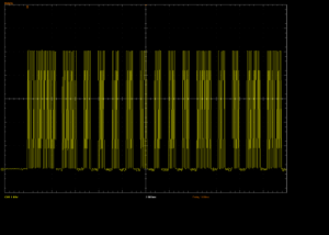
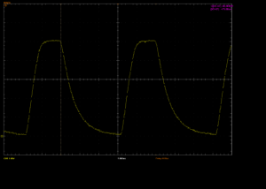
Both oscilloscope images above show the signal at pin 2 of the Arduino using the circuit above. Click on the images for a larger and better view. You will note that the captured signal in the first image is a full 0v -> 5v swing & in the second image the captured carrier frequency is exactly 40 kHz or 25 microseconds.
We have also provided a download link to the software required for this project. Essentially this software will just report the signal timings on the serial port, which can be read on the Arduino serial monitor or any serial program. Unlike a standard IR receiver, the full modulated carrier signal is presented at pin 2, which means that we need to include some software logic to filter out the carrier pulses within the marks.
You should consider using this circuit if:
- You don’t have a quality IR receiver available.
- You don’t want to wait for it to arrive via post.
- Your existing IR receiver is not working with your remote control.
- You believe your cheapo IR receiver is missing some of the IR signal being transmitted (not uncommon).
Performance
So how well does it perform? Well we have provided some sample captures for you to see (click to view) for yourself. For the test we sent the same signal at all common carrier frequencies (30, 33, 36, 38, 40 & 56 kHz). To measure the carrier frequency for less common B&O 455kHz frequencies, you can customise the code provided for use on a faster MCU.
Arduino code
We are making this source code freely available and only ask, in return, that you credit AnalysIR and post a link to this blog. Feel free to improve the code or indeed turn it into an Arduino library. We haven’t spent much time optimising this code, but it worked well for us. Click here to download the source code for Arduino.
In general, we would always use quality IR receivers from manufacturers like Vishay & avoid the cheaper ones that come without data sheets or model numbers. However, if you don’t have a standard IR receiver then the poor maker’s IR receiver is a compelling alternative.
If you manage to get this circuit working, do leave some feedback in the comments or forum.
Caution: please verify that you are achieving the voltages described above before connecting to your MCU. The circuit above is designed for 5v logic levels but should also work at 3.3v logic levels, with the same value components. We have also noticed that some IR remotes emit weak signals or have their IR Led embedded too far inside the casing to allow close proximity. Of course, new batteries will always help with this circuit.
Remember, if you are serious about Infrared remote control, then make sure you get your own copy of AnalysIR.
2 thoughts on “Poor maker’s Infrared receiver #2”