Many electronics enthusiasts will be familiar with how Infrared receivers demodulate IR signals. In this post we show a visualisation of the time lag and distortion of the signals as they pass through the IR receiver for demodulation and noise filtering. Most DIY projects use the raw timings from the IR receiver to decode individual signals. However, not many will be aware that IR receivers can distort the signal timings by significant amounts. Fortunately, common IR decoders take this into account and compensate for timing distortions introduced by infrared demodulators / receivers.

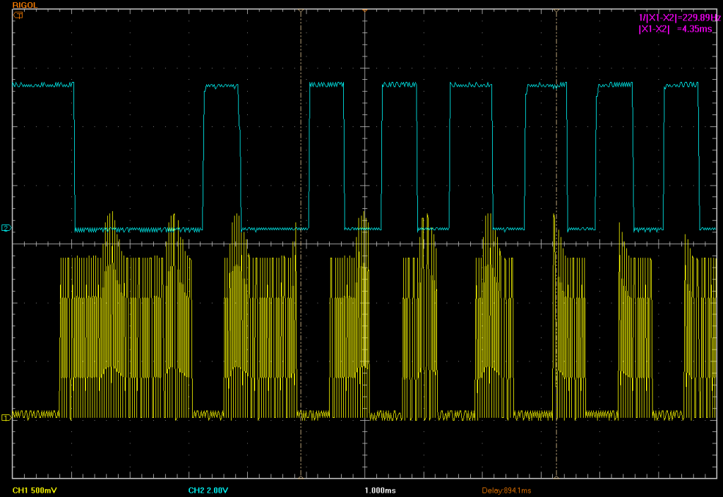
The oscilloscope screen-shot shows an overview of an IR signal. The yellow trace shows the modulated signal captured at the IR LED emitter. The blue trace shows the same demodulated signal output by the IR Receiver. Observant readers will notice that the blue (demodulated) signal is inverted from the yellow (modulated) signal, which is typical behaviour for most IR receivers. (Ignore the spikes on the yellow modulated signal, which are due to noise and the lack of a current limiting resistor on the IR LED). Now let’s zoom in a bit on the same signal.

The screen shot above, shows the start pulse of the signal and as we can observe from the cursor measurement on the trace (X1-X2), the delay of the signal passing through the IR receiver is circa 247 micro-seconds. A quick check of the data sheet for the IR receiver we used, reveals that the delay above should be between 175 and 375 microseconds at the 40kHz carrier frequency used. (Between 7/frequency and 15/frequency). So we are well within the rated specification of the device.
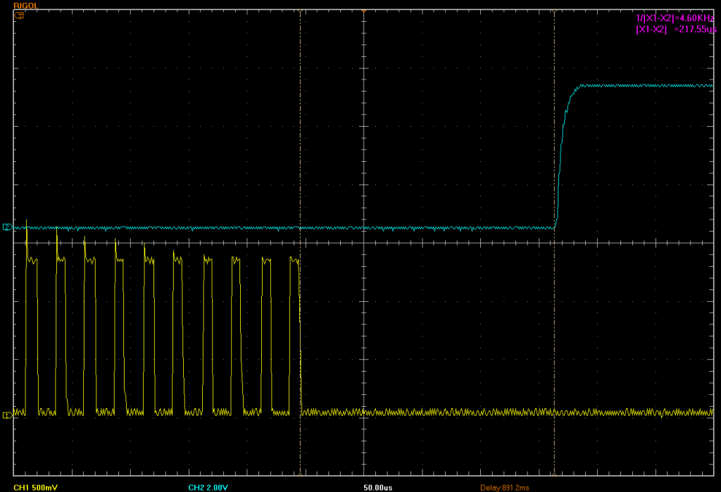
Now let’s zoom in to the end of the same first pulse.

The screen-shot above shows the lag at the end of the first pulse in the original signal. Here we can also observe from the cursor measurement on the trace (X1-X2), the delay of the signal passing through the IR receiver is circa 217 micro-seconds delayed.
Wow – that’s a whopping 30 microsecond signal distortion (247-217) on just one modulated pulse. Well it is really not that bad at all, because both marks (modulated pulses) and spaces (no signal) end up being distorted and over the length of the overall signal they tend to cancel each other out. The example, presented above is pretty good behaviour actually, as many receivers can show distortions of up to 100 microseconds and more, depending on a variety of factors. The distortion observed in this signal is also well within the rated specification for the device under test.
Looking at the data sheet again, tells us that this signal distortion can in fact range from -125 microseconds to +150 microseconds (@40kHz modulation) for marks. This would be reversed in the case of spaces.
The popular open source IR libraries for Arduino, IRremote & IRLib, both make allowances for distortion. IRremote defaults to a 100 uSec adjustment and IRLib has defaulted to 50 uSec in the latest release. We prefer to use 30 microseconds in our own projects, based primarily on our preferred receiver. Either way this parameter is configurable in each implementation. Given that many decoders allow for an error margin of up to 25%, a distortion of 30-100 microseconds is easily tolerable, as would the maximum rated distortion above of 150 microseconds.
Tip: When decoding unknown signals or protocols, using the combined time for subsequent marks and spaces can be a better indication of signal timings, than individual marks or spaces (which we know from above can be distorted). This is because the timings from the start of a mark to the end of a space are much more accurate than individual marks and spaces – when measured at the output of the IR receiver. Even better is to measure the timings of several similar mark/space pairs in sequence, which usually reveals signal timings to an accuracy of just a few microseconds.
Links:
SB-Projects – IR Remote Control Theory
Vishay TSSP58038 – IR receiver (light barrier) used in test
One thought on “Infrared Receivers – signal lag and distortion”